
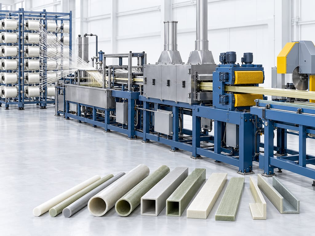
FRP Pultrusion Process: How Fiberglass Profiles Are Made
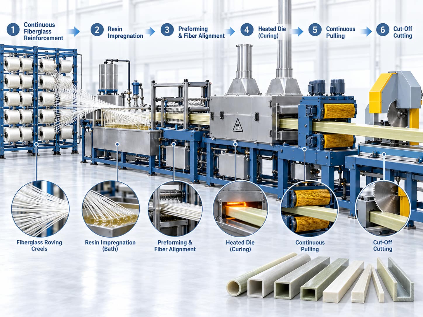
The FRP pultrusion process converts continuous fiberglass reinforcement and a resin system into a cured profile with a consistent cross-section. The defining action is pulling: reinforcement moves through impregnation and guiding equipment, enters a heated forming die, cures into the required section, and continues to a cutting station.
This guide explains the sequence, the purpose of the main process stages, and the manufacturing limits engineers should understand before specifying a pultruded fiberglass profile. Equipment layouts vary by manufacturer, profile geometry, material system, and production plan, so the sequence below describes common process functions rather than one mandatory line configuration.
What Is the FRP Pultrusion Process?
Pultrusion is a continuous composite-manufacturing method used to make profiles whose cross-section remains substantially consistent along their length. Glass reinforcement is supplied continuously, combined with a thermosetting resin system, organized for the required section, and pulled through a heated die. The die forms the cross-section and supports cure. A pulling unit maintains movement through the line, and the cured profile is then cut or otherwise prepared for the next operation.
The name helps distinguish pultrusion from extrusion. In conventional extrusion, material is pushed through a die. In pultrusion, the reinforcement and developing composite profile are pulled through the line. Both processes can produce continuous sections, but their materials, forming behavior, and equipment principles are different.
The finished profile is not defined by the die alone. Reinforcement type and placement, resin formulation, impregnation, preforming, die design, cure conditions, pulling control, and downstream handling all influence the result. That is why a profile drawing must be reviewed together with its material and manufacturing plan.
Continuous Fiberglass Reinforcement
A pultrusion line begins with reinforcement supplied in continuous form. Rovings provide long, aligned glass filaments. Mats, fabrics, veils, or other compatible reinforcement forms may also be introduced when the section and performance requirements call for them. The exact combination is application- and process-specific.
Rovings and Lengthwise Reinforcement
Continuous rovings are guided from creels toward the impregnation and forming stages. Their placement can support performance primarily along the profile length, but the finished behavior still depends on the entire laminate construction and cross-section.
Additional Reinforcement Forms
Mats or fabrics may be incorporated to support transverse behavior, surface requirements, local stability, or handling through the line. Not every profile uses the same reinforcement architecture.
Fiber arrangement matters because composite properties are directional. Reinforcement should be distributed through the section according to the loading, geometry, surfaces, and manufacturing requirements. Poor positioning, distortion, or inconsistent feed can affect dimensions, appearance, and performance. No single reinforcement layout is appropriate for every rod, tube, bar, or custom section.
Resin Impregnation
The reinforcement must be combined with a resin system so the fibers become part of a cured composite. Depending on the equipment and material plan, impregnation may use a resin bath or another controlled wet-out arrangement. The objective is to distribute resin through the reinforcement before the material enters the final forming and curing stage.
Polyester, vinyl ester, and epoxy are resin families already associated with DISLAB’s FRP profile information. Selection is not based on the resin name alone. Viscosity, cure behavior, profile geometry, reinforcement architecture, operating environment, surface requirements, and production setup all matter. For qualitative selection context, see the guide to polyester, vinyl ester, and epoxy resin for FRP parts.
Preforming and Fiber Alignment
After impregnation, guides and preforming elements organize the reinforcement before it enters the heated die. This stage transitions a broad collection of rovings, mats, or fabrics toward the compact arrangement required by the final profile. It may also help manage excess resin and prevent reinforcement from folding, bunching, or drifting from its intended position.
Preforming is especially important for hollow sections, corners, wall transitions, and custom geometries. The reinforcement must travel through the line without damaging fibers or creating unstable accumulation. Guide design, entry geometry, reinforcement tension, and material handling are therefore considered together.
The term “preforming” describes a process function, not one universal machine. Some lines use multiple guide plates or staged forming elements; others integrate functions differently. The relevant engineering question is whether the reinforcement can be positioned consistently and delivered into the die in a controlled condition.
Heated Die Forming and Curing
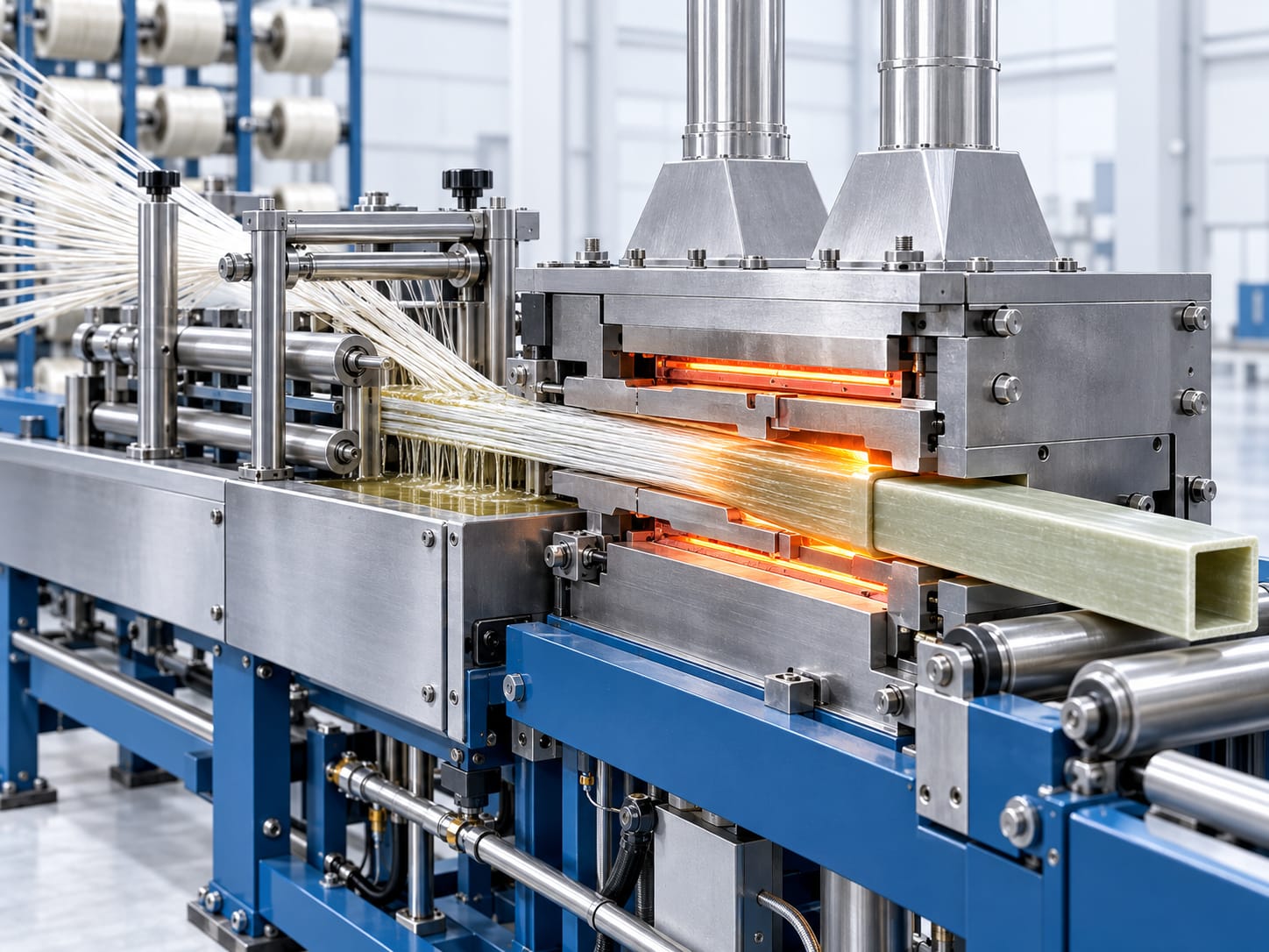
The heated die establishes the profile’s constant cross-section and provides the environment in which the resin system cures. As the impregnated reinforcement enters the die, the material is compacted and constrained by the tooling. It exits as a rigid composite section corresponding to the intended die geometry.
Tooling is central to custom pultrusion because the die must support material entry, forming, heat transfer, cure, release, and continuous movement. A cross-section that looks simple on a drawing may still require careful review of wall transitions, internal openings, corner geometry, reinforcement paths, and the way material enters the die.
Die temperature, line speed, cure behavior, and pulling conditions interact, but universal values would be misleading. Suitable settings depend on the resin formulation, reinforcement, section size, tooling, equipment, and required output. Those parameters belong in the manufacturer’s controlled process plan rather than a general article.
Continuous Pulling
A pulling unit moves the reinforcement and cured profile through the manufacturing line. Different machines may use reciprocating clamps, caterpillar-style pullers, or other arrangements suitable for the section and production setup. The equipment should maintain controlled movement without damaging or distorting the emerging profile.
This pulling action is the defining characteristic of pultrusion. It draws the materials through impregnation, preforming, and the heated die as one continuous sequence. Pulling conditions must be coordinated with cure and tooling behavior; simply increasing movement without regard to material response would not ensure a properly cured or dimensionally acceptable profile.
Cutting to Length
Once the profile has cured and moved beyond the pulling stage, it can be cut to the specified length. The cut-off arrangement depends on the profile, line, production method, and required edge condition. Cut length, squareness, surface protection, dust control, and downstream handling may all be part of the production plan.
Pultrusion can create a continuous profile, but shipment and assembly usually require defined pieces. There is no single standard length that applies to every project. Drawing requirements, transport, packaging, site handling, and subsequent machining should be considered when specifying the finished length.
Secondary Machining After Pultrusion
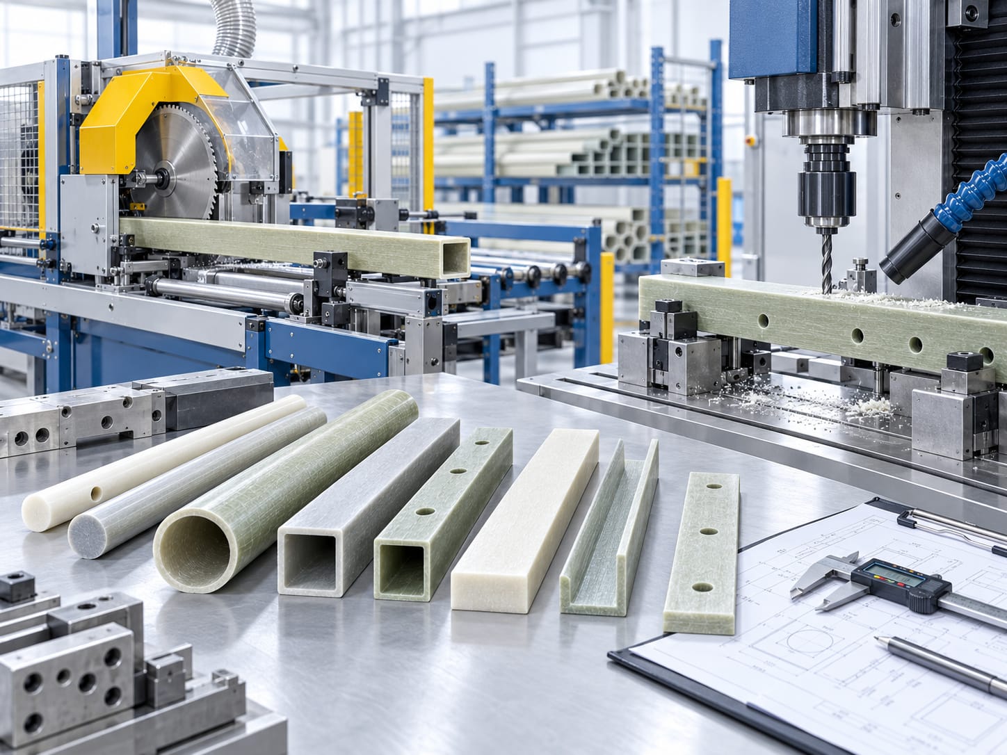
The die produces the constant cross-section, not every feature needed for assembly. Drilled holes, slots, notches, local relief, trimmed areas, controlled end faces, and machined interfaces may be added after pultrusion. CNC machining or dedicated fixtures may be considered where feature location and repeatability are important.
- Cut-to-length preparation and end finishing
- Drilling and controlled hole patterns
- Slots, notches, and localized trimming
- Machined interfaces for fit or fastening
- Inspection of dimensions, surfaces, and finished features
Machining requirements should be included on the drawing. Feature size, position, edge distance, tolerance, laminate construction, clamping method, and acceptance criteria can affect the practical operation. Dust and tool-wear controls are also relevant when machining fiberglass composites. Use the drawing guide to specify profile dimensions, tolerances and machining features for project review.
What Profile Shapes Can Be Pultruded?
Representative constant-cross-section shapes include solid rods, round tubes, square and rectangular tubes, flat bars, angles, channels, and drawing-based custom sections. A consistent cross-section is the common principle, but that does not mean every theoretically constant shape is practical.
Feasibility depends on how reinforcement can be guided, how resin reaches the reinforcement, how the section enters and releases from the die, how heat moves through the section, and whether the geometry can cure and pull consistently. Internal openings, sharp transitions, wall relationships, and surface expectations may need special review.
Ground-support applications can use GFRP rock bolt systems, combining pultrusion-based fiberglass bolts with compatible nuts and bearing plates. Component matching and project-specific mechanical requirements should be reviewed together.
For commercial information about available profile families, material options, customization, machining, and quotation inputs, use the custom pultruded fiberglass profiles sourcing page.
What Controls the Quality of a Pultruded FRP Profile?
| Control area | Why it matters |
|---|---|
| Reinforcement placement | Supports the intended material distribution and helps reduce local distortion or inconsistency. |
| Resin impregnation | Helps the resin reach and bind the reinforcement before cure. |
| Preforming and guidance | Organizes reinforcement for entry into the die and the required cross-section. |
| Cure control | Coordinates resin reaction, profile movement, and the formation of a stable section. |
| Tooling condition | Affects profile geometry, surface condition, release, and process stability. |
| Pulling and handling | Maintains continuous movement while limiting damage or distortion. |
| Cutting and machining | Influences length, edge condition, hole or slot geometry, and installation readiness. |
| Inspection | Confirms the agreed dimensions, appearance, machined features, and other drawing requirements. |
Quality requirements should be defined by the drawing, purchase specification, and agreed inspection plan. Mechanical, electrical, environmental, or third-party testing should be specified when needed. A general process description cannot establish product-specific acceptance values.
Where Pultrusion Works Well — and Where It Does Not
Good Fit for Pultrusion
Long products with a consistent cross-section are the natural fit. Rods, tubes, bars, channels, angles, and feasible custom sections can benefit from a continuous manufacturing route when the material and geometry can be guided, formed, cured, and pulled reliably.
When Another Method Is Needed
Large shells, housings, covers, deep three-dimensional forms, curved surfaces, integrated bosses, and parts with major changes in cross-section generally require a molding or fabrication method designed for that geometry.
Pultrusion should not be treated as a substitute for every FRP process. If the part is a molded enclosure, cover, panel, shell, or other non-constant geometry, review DISLAB’s custom molded and fabricated FRP capabilities. Separating these routes early helps avoid forcing a geometry into an unsuitable process.
From Profile Drawing to Production
A useful manufacturing review begins with the cross-section and application rather than an assumed set of production parameters. The following information helps a pultruder evaluate the material and tooling route:
- Dimensioned cross-section drawing and units
- Overall profile or finished-part length
- Critical dimensions and functional interfaces
- Prototype, initial-order, and expected repeat quantity
- Resin preference or environmental exposure requirements
- Reinforcement or directional-performance requirements, if already specified
- Drilling, slotting, trimming, or other machining details
- Surface, identification, inspection, packaging, and destination requirements
The review may identify changes needed for reinforcement flow, tooling, cure, machining, or inspection. It may also show that the geometry belongs to a different composite process. Final feasibility is established by the complete drawing, material system, process setup, quantity, and application conditions—not by the profile name alone.
Frequently Asked Questions
What is the difference between pultrusion and extrusion?
Pultrusion pulls continuous reinforcement and resin through a forming and curing line. Extrusion generally pushes a material through a die. The equipment, material behavior, and process principles are different even though both can produce continuous sections.
Why does pultrusion produce a constant cross-section?
The developing composite moves continuously through a fixed die cavity. That cavity forms the same section along the profile length. Major lengthwise geometry changes normally require machining, assembly, or another manufacturing process.
Can pultruded fiberglass profiles be machined after production?
Yes, project-dependent operations can include cutting, drilling, slotting, trimming, end finishing, and CNC machining. The feature design, laminate, tolerance, edge condition, and inspection requirements should be reviewed together.
Which resin systems are used in FRP pultrusion?
Polyester, vinyl ester, and epoxy are relevant resin families in DISLAB’s current profile information. The selected grade and formulation must suit the pultrusion process, reinforcement, geometry, environment, and required verification.
Can custom FRP profile shapes be pultruded?
Custom constant-cross-section profiles may be feasible, but manufacturability depends on reinforcement paths, wall relationships, internal openings, tooling, cure behavior, surface needs, and production economics.
When is pultrusion not suitable for an FRP part?
It is generally not the natural choice for deep three-dimensional parts, large shells, curved housings, or components whose cross-section changes substantially along their length. Those parts should be reviewed for an appropriate molding or fabrication route.
Review a Pultruded Profile Requirement
If you are moving from process research to a real profile, review the available shape families, material considerations, machining options, and drawing information required for sourcing.
View Custom Pultruded FRP ProfilesThis article provides general manufacturing guidance. Profile feasibility, process settings, material selection, dimensions, and inspection requirements must be confirmed for the actual design and application.