
Pultruded FRP Profile Dimensions, Tolerances and Machining Guide
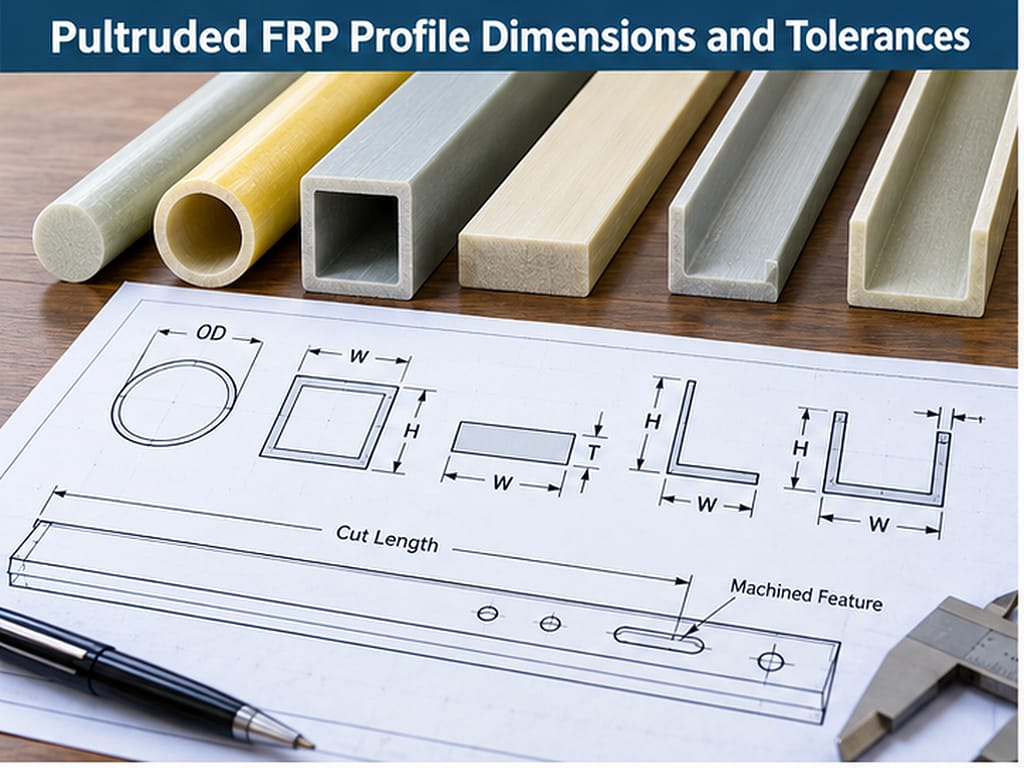
A useful pultruded FRP drawing does more than name a profile shape. It identifies the dimensions that define the continuous cross-section, the features that control fit and assembly, the required cut length, and any holes, slots, or machined interfaces that must be produced after pultrusion.
This guide explains how engineers and buyers can communicate those requirements without assuming that one tolerance table applies to every fiberglass profile. Achievable results depend on the complete profile, material, tooling, fabrication, and inspection plan.
Why Dimensions and Tolerances Matter in Pultruded FRP Profiles
Four groups of requirements should be separated at the drawing stage. Nominal profile geometry describes the intended constant cross-section. Critical mating dimensions control how the profile fits another component. Cut length defines the finished piece rather than the continuous output. Machined features add local geometry that the pultrusion die does not create.
Nominal Geometry
Width, height, diameter, wall thickness, radii, flanges, and internal openings describe the cross-section that travels through the die.
Functional Dimensions
Interfaces, mating surfaces, clearance areas, and assembly datums deserve clear identification because they affect fit and performance.
Finished Length
Cut length, end condition, and squareness requirements belong to the downstream finishing plan, not only the profile cross-section.
Secondary Features
Holes, slots, notches, end cutouts, and localized mounting features normally require drilling, routing, cutting, or another controlled operation.
A tolerance should have a functional reason. Applying the tightest possible requirement to every dimension can complicate tooling, machining, inspection, and quotation without improving the assembly.
Start With the Profile Cross-Section Drawing
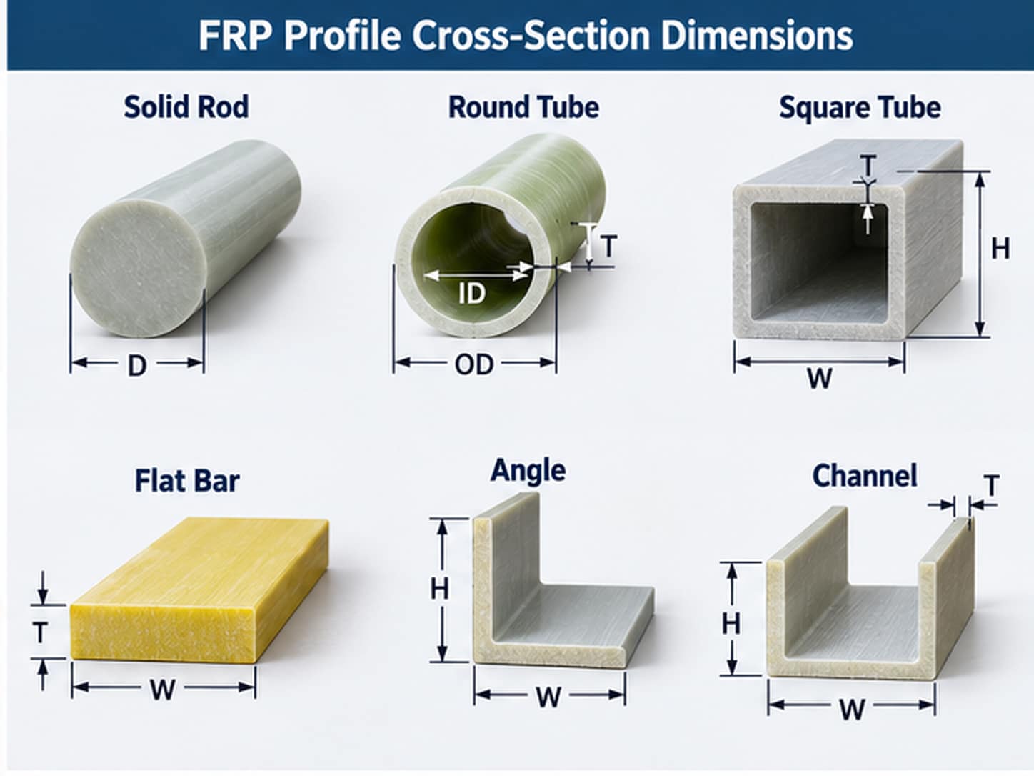
A dimensioned drawing is more reliable than a verbal description such as “fiberglass tube” or “custom channel.” For a round tube, define the outside diameter, inside diameter or wall requirement, and any surfaces that mate with other parts. For a square or rectangular tube, define the outside width and height, wall relationships, corner geometry, and internal opening. Flat bars, angles, channels, and custom sections require the same disciplined approach.
Show radii, flange widths, web dimensions, open-channel dimensions, and critical wall transitions where they affect the intended section. Identify units and drawing revision. If a dimension is for reference only, mark it accordingly rather than allowing it to conflict with controlled dimensions.
Which Dimensions Are Formed by the Pultrusion Die?
The pultrusion die forms the continuous cross-section as the reinforced resin system moves through the tooling and cures. Dimensions that remain consistent along the profile length are therefore candidates for die-controlled geometry, subject to material flow, reinforcement placement, cure behavior, release, and tooling feasibility.
Conventional pultrusion does not directly create major shape changes along the length. A local hole, isolated slot, end relief, or mounting cutout is not part of a constant die cavity. Such features may be machined after the continuous profile has been produced.
For a detailed explanation of reinforcement supply, impregnation, preforming, the heated die, pulling, and cutting, see how the FRP pultrusion process works.
Why FRP Tolerances Depend on Profile Geometry
There is no responsible universal tolerance value for every pultruded FRP profile. A balanced standard structural shape and an asymmetrical custom section can place different demands on reinforcement distribution, tooling, cure, and dimensional control. Overall size, wall thickness, hollow geometry, flange relationships, corner transitions, and reinforcement architecture all influence how a section behaves during manufacture.
The resin system, die design, tooling condition, pull direction, process settings, cut length, and measurement method also matter. A formed cross-section dimension should not automatically receive the same tolerance as a drilled hole or machined interface. Even dimensions that look similar on two drawings may require different manufacturing and inspection plans.
Where DISLAB-specific capability data has not yet been confirmed for the actual section, the correct approach is to mark critical dimensions and request a feasibility review. The supplier can then evaluate the requirement against the drawing, profile geometry, material system, tooling, and planned secondary operations.
Cut Length and End Preparation
Pultrusion produces a continuous section, but most projects require pieces cut to a defined length. The drawing should state finished length, tolerance priority, required end condition, and whether end squareness affects assembly. If an allowance is required for later trimming or customer-side fitting, identify it explicitly rather than embedding it in an unclear overall dimension.
Long profiles also need a packaging and handling review. Finished length can affect bundle design, surface protection, transport, unloading, storage, and the practical sequence of subsequent machining. Do not assume a standard supply length without confirming the actual project and logistics plan.
Drilling Pultruded Fiberglass Profiles
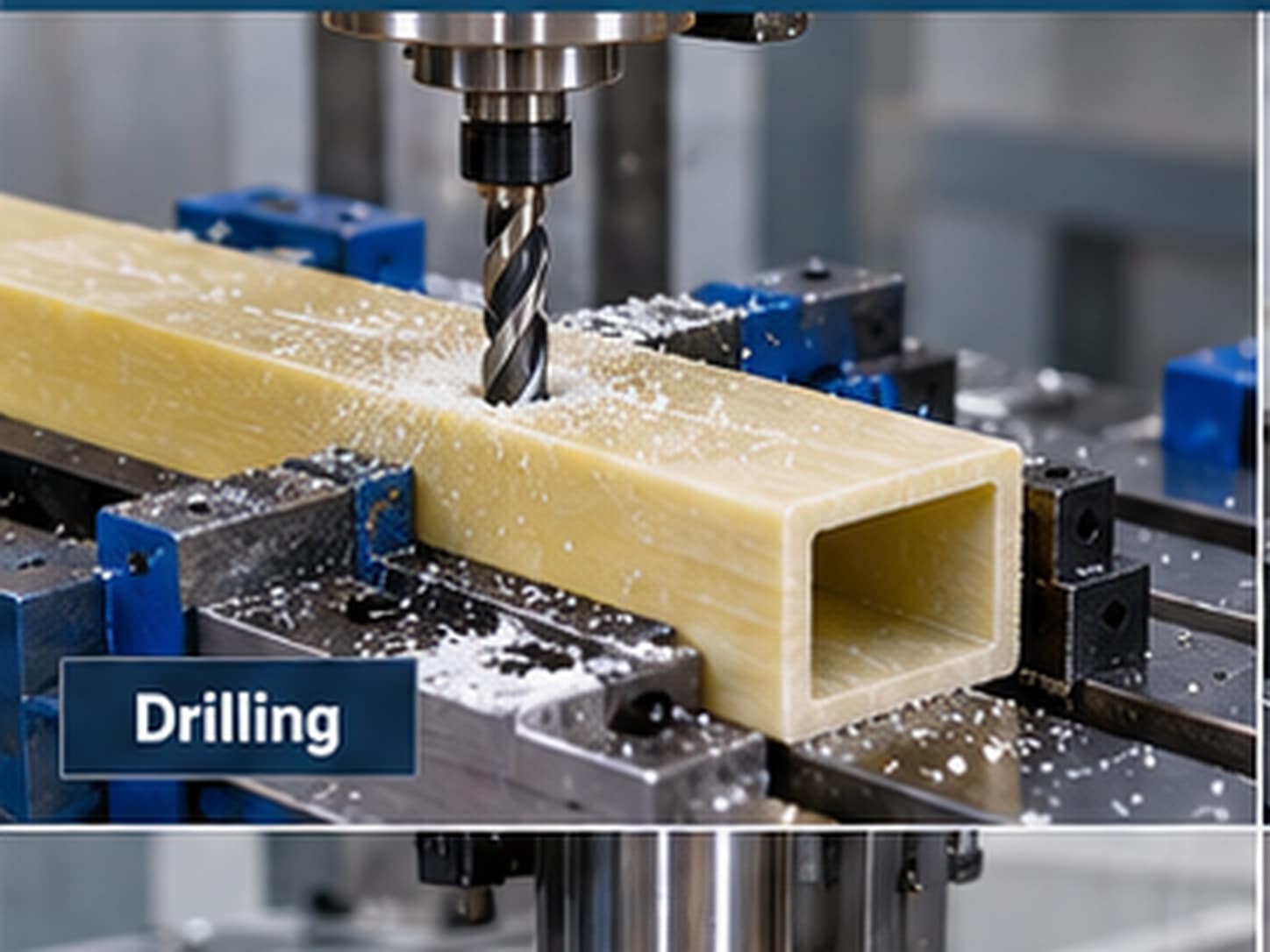
Holes are commonly produced after pultrusion because their location changes along the profile length. The drawing should define hole diameter, location, datum references, quantity, and the surfaces from which the feature is controlled. Edge distance and nearby geometry should be reviewed together with the profile wall, reinforcement, fastener arrangement, and load path.
Workholding and support matter, especially for hollow sections or features near an edge. The fabrication method should limit unwanted movement and help control the exit condition of the hole. Fiberglass is abrasive to cutting tools, and drilling can expose or disturb reinforcement at the machined edge. Tool selection, support, process condition, and inspection must therefore be matched to the actual material and production quantity.
This guide does not prescribe a universal drill speed, feed, hole allowance, or minimum edge distance. Those values require review of the profile, laminate, tool, hole function, and acceptance criteria.
Slots, Notches and Other Machined Features
Secondary machining can add slots, notches, end cutouts, mounting clearances, localized trimming, and other features that do not run continuously through the profile. Each feature should be located from defined datums and evaluated for its effect on remaining material, reinforcement paths, assembly loads, and edge condition.
Machining capability is not unlimited. A feature that removes too much material, intersects a corner, leaves an unsupported wall, or conflicts with the reinforcement arrangement may require redesign, added support, an assembled detail, or another manufacturing route. Early drawing review is preferable to treating every metal-part feature as directly transferable to FRP.
CNC Machining of FRP Profiles
CNC equipment may be useful when a project requires repeatable hole patterns, routed slots, localized dimensional features, mating details, or consistent assembly preparation. A controlled program can support repeatability, but the program is only one part of the manufacturing plan. Fixturing, profile variation, tool condition, dust and chip management, and the chosen inspection method remain important.
Do not infer a machining tolerance from the fact that CNC equipment is used. The achievable result is still governed by the complete system: the as-pultruded profile, datum strategy, workholding, cutting method, tool wear, feature geometry, and measurement approach.
Surface and Edge Considerations After Machining
Cutting, drilling, or routing can expose fibers and create an edge condition different from the original profile surface. Requirements may include a clean cut, controlled breakout, deburring or edge dressing, removal of loose fibers, or project-specific finishing. The acceptable result should be described where appearance, handling, bonding, sealing, or assembly depends on it.
Machining also produces fiberglass dust and tool wear. Fabrication planning should include suitable controls for the selected operation and facility. If cut or machined edges require additional treatment for the application, define that requirement during quotation rather than assuming it is included.
Dimensional Inspection
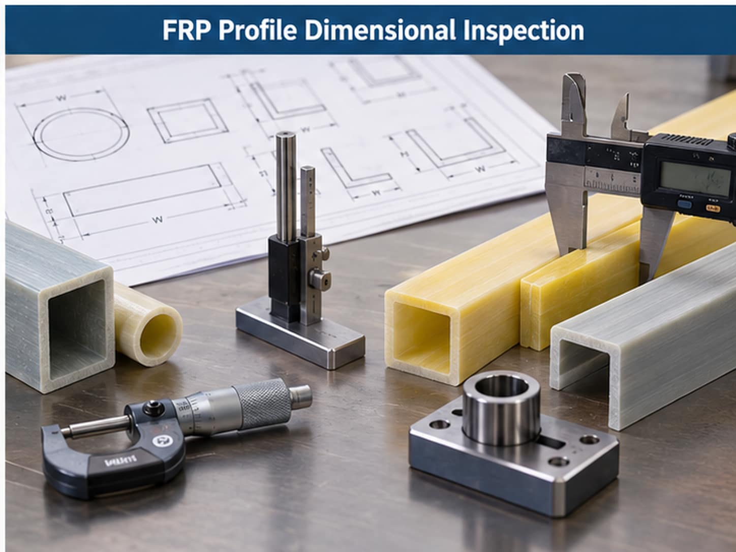
Inspection should follow the drawing and the function of the finished profile. Calipers, gauges, fixtures, templates, and other suitable methods may be used depending on the dimension and required confidence. The measurement method should match the characteristic: an overall cross-section dimension, a hole location, a cut length, and an assembled fit may require different approaches.
Identify critical characteristics, reference datums, measurement locations, and any reporting requirement. Sampling, first-article review, or project-specific inspection can be discussed according to quantity, risk, and buyer requirements. This article does not claim that every instrument, report, or inspection system is included by default.
How to Specify Tolerances on an RFQ Drawing
| Drawing item | What to communicate | Why it matters |
|---|---|---|
| Critical dimensions | Identify dimensions that control fit, alignment, fastening, sealing, or function. | Focuses manufacturing and inspection effort where it has functional value. |
| Reference dimensions | Mark informational dimensions so they do not create conflicting controls. | Reduces ambiguity during quotation and inspection. |
| General dimensions | Define the nominal cross-section and state which drawing requirement governs. | Establishes the intended profile without over-controlling every feature. |
| Machined dimensions | Separate drilled, routed, cut, and finished features from as-pultruded geometry. | Allows the appropriate production and inspection method to be selected. |
| Hole and slot locations | Use clear datums and identify the mating or fastening function. | Supports repeatable layout and assembly review. |
| Cut length | State finished length, end condition, and any functional squareness requirement. | Connects line output to packaging and final installation needs. |
Avoid making every dimension equally tight. If a requirement does not affect function, assembly, appearance, or acceptance, a more practical tolerance may reduce tooling, fabrication, and inspection complexity. Mark what is critical and allow the supplier to review the remaining dimensions against the proposed manufacturing route.
When Secondary Machining Is Better Than Tooling-Controlled Geometry
It can be more practical to pultrude a stable constant section first and add isolated features afterward. Hole patterns that vary by assembly, slots used only at selected locations, end relief, localized interfaces, and mounting cutouts are typical candidates for secondary operations. This approach avoids trying to create non-continuous geometry with a continuous die.
The choice is project-specific. High repeat quantity, feature complexity, remaining section strength, fixture design, inspection needs, and total manufacturing economics should be considered together. In some cases a revised cross-section, separate bracket, bonded component, or different composite process is more appropriate.
Information to Send for a Custom Profile Review
- Dimensioned cross-section drawing with units and revision
- Nominal dimensions and clearly marked critical tolerances
- Finished profile length and end-condition requirements
- Prototype, initial-order, and expected repeat quantity
- Resin, reinforcement, or material requirements if already specified
- Operating environment and the profile’s role in the assembly
- Hole, slot, cutout, trimming, and other machining details
- Inspection, documentation, packaging, and destination requirements
For available profile families, custom manufacturing scope, material considerations, and quotation inputs, review DISLAB’s custom pultruded FRP profiles page.
Frequently Asked Questions
Can pultruded FRP profiles be CNC machined?
Yes, CNC machining may be considered for repeatable holes, slots, cutouts, mating features, and assembly preparation. Feasibility and achievable results depend on the profile, material, feature geometry, fixturing, tooling, and inspection plan.
Can holes be drilled after pultrusion?
Yes. Drilling after pultrusion is a common way to add localized holes that cannot be formed continuously by the die. Define hole size, position, datums, edge relationships, and function on the drawing.
Can pultruded profiles have tight tolerances?
Critical dimensions may be reviewed for tighter control, but no single answer applies to every profile. Geometry, material system, reinforcement, tooling, secondary machining, and measurement method must be evaluated together.
Are hollow fiberglass profiles harder to control dimensionally?
Hollow sections introduce internal openings, wall relationships, corners, and support considerations that can affect tooling and measurement. The complete section should be reviewed rather than assuming the same controls as a solid profile.
Should holes be included in the pultrusion die?
Localized holes normally do not belong to the constant die cavity because they occur only at selected positions along the length. They are generally considered as secondary operations, subject to feature and process review.
Can a pultruded profile change cross-section along its length?
Conventional pultrusion is intended for a substantially constant cross-section. Major lengthwise changes generally require machining, assembly, or another manufacturing process.
Prepare a Pultruded Profile Drawing for Review
Send the cross-section, critical dimensions, length, quantity, application, machining features, inspection requirements, and destination so the manufacturing route can be evaluated against the actual project.
Review Custom Pultruded FRP ProfilesThis guide provides general specification guidance. Final dimensions, tolerances, machining methods, inspection requirements, and production feasibility must be confirmed for the actual drawing and material system.