
Hand Lay-Up vs RTM vs SMC: Choosing a Fiberglass Molding Process
Choosing a fiberglass molding process is not simply a choice between a basic method and a more advanced one. The practical decision depends on the part, the production program, the required surfaces, the degree of repeatability, and the tooling investment the project can support.
The buyer’s question: When should an OEM consider hand lay-up, resin transfer molding, or SMC compression molding for a fiberglass part?
Process selection affects more than the molding operation. It influences mold construction, laminate strategy, draft and edge details, insert design, trimming, inspection, and the cost structure of the finished program. A process that is practical for a large prototype shell may be inefficient for a stable repeat-volume housing. A process that offers strong repeatability may require tooling that cannot be justified while the design is still changing.
The comparison below is a selection guide, not a substitute for design-for-manufacturing review. Resin system, reinforcement, geometry, surface class, structural requirements, and the manufacturer’s equipment can all change the final recommendation.
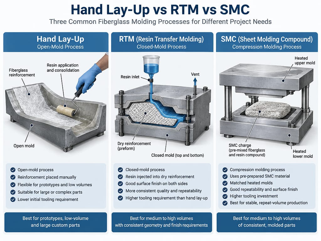
Quick Comparison: Hand Lay-Up vs RTM vs SMC
| Selection factor | Hand lay-up | RTM | SMC compression molding |
|---|---|---|---|
| Mold type | Typically an open, single-sided mold | Closed mold with two tooling surfaces around a dry reinforcement preform | Matched, generally heated compression-molding tool |
| Initial tooling requirement | Generally lower relative to closed matched-tool processes | Moderate to higher, with sealing, resin-flow, and closed-cavity planning | Typically higher because robust matched tooling and press compatibility are central to the process |
| Production-volume suitability | Often practical for prototypes, lower quantities, and custom work | Often considered for recurring production that can justify closed tooling | Usually strongest for stable repeat-volume programs |
| Geometry flexibility | Flexible for many large or custom shapes, subject to access and laminate placement | Depends on closed-mold filling, preform placement, draft, sealing, and demolding | Depends on material flow, charge placement, matched-tool geometry, and press constraints |
| Surface quality | The mold side can be controlled; the open side normally reflects manual finishing and laminate work | Offers the opportunity for controlled surfaces on both mold faces | Can produce repeatable molded surfaces when material, tool, and process are well matched |
| Repeatability | More dependent on operator skill and process discipline | Generally more controlled after the mold, preform, and resin-flow plan are established | Generally strong for a stable product and qualified molding process |
| Production rate | Labor-intensive and generally slower | Can support more repeatable recurring production than manual open molding | Often selected when repeat-production efficiency is important |
| Part-size flexibility | Often practical for large shells and covers where manual access is available | Limited by closed-tool handling, resin-flow design, and equipment | Limited by press capacity, tool size, handling, and charge-flow requirements |
| Design-change flexibility | Relatively high before committing to more complex tooling | Changes can require closed-tool and flow-plan revisions | Best when geometry and production requirements are stable |
| Best suited for | Custom shapes, prototypes, large parts, and lower-volume programs | Recurring parts needing controlled closed-mold geometry and repeatability | Stable repeat programs suited to compression molding and matched tooling |
What Is Hand Lay-Up?
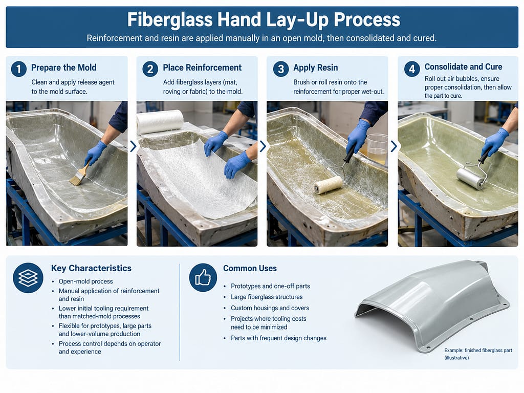
Hand lay-up is an open-mold process. Release preparation and any specified surface layer are applied to the mold, reinforcement is positioned manually, and liquid resin is applied or worked into the reinforcement. The laminate is consolidated to wet the fibers, remove avoidable trapped air, and build the required construction before cure.
Because the process normally uses one primary mold surface, its tooling barrier is generally lower than that of RTM or SMC matched tooling. That does not make tooling unimportant. Mold stability, surface preparation, laminate access, edge definition, cure behavior, and trimming references still affect part quality.
Hand lay-up leaves more production variables in manual operations. Reinforcement placement, resin distribution, laminate consolidation, and local build-up depend on work instructions, operator technique, inspection, and process control. The mold-side surface may be well defined, while the open side typically requires different expectations or secondary finishing.
When Hand Lay-Up Makes Sense
Hand lay-up is often considered for prototypes, lower quantities, large fiberglass shells, project-specific housings, and components whose geometry or demand does not support a more complex matched tool. It can also be useful while a design is evolving, because some changes may be more practical before a production program is locked into closed tooling.
Part size alone does not select the process, but manual open molding can be practical where very large matched tools and press equipment would be difficult to justify. The trade-off is greater labor input and stronger dependence on documented laminate procedures and inspection.
A fiberglass racing-seat shell example shows how hand lay-up can be used for a shaped component where tooling, laminate placement, trimming, and finish all need coordinated control.
What Is RTM?
Resin Transfer Molding, or RTM, is a closed-mold process. Dry reinforcement is arranged as a preform and placed in the mold. The mold is closed, and mixed resin is introduced into the sealed cavity so that it flows through and impregnates the reinforcement before cure.
The closed cavity can provide better control of both molded surfaces, part thickness, edge geometry, and repeat production than a manual open-mold route. Achieving that result requires planning for preform stability, resin viscosity, injection location, vents, sealing, fill behavior, cure, and demolding.
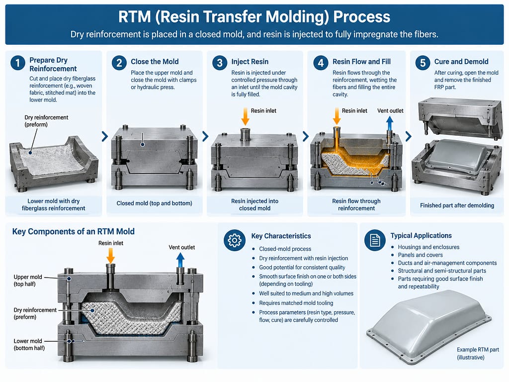
RTM should not be used as a generic name for every vacuum-assisted composite process. In vacuum infusion, a flexible vacuum bag commonly closes the laminate against a one-sided mold while vacuum draws resin through the reinforcement. RTM uses a closed mold cavity. Vacuum-assisted RTM variants use vacuum as part of a closed-mold resin-transfer strategy, but their tooling and pressure conditions should still be defined clearly.
When RTM Makes Sense
RTM can be considered when a recurring production program needs more consistent geometry, controlled molded surfaces, or better repeatability than a manual open-mold process is likely to provide. The part and production demand must justify two-sided tooling and the work required to establish a reliable preform and resin-flow plan.
Closed tooling does not automatically make every difficult geometry practical. Deep draws, sharp transitions, variable laminate thickness, trapped-air risk, complex inserts, and difficult demolding can complicate the process. These factors should be reviewed before the mold is designed.
What Is SMC Compression Molding?
Sheet Molding Compound, or SMC, is a prepared molding material containing resin, chopped fiber reinforcement, and formulation ingredients supplied in sheet form. A measured charge is placed in a matched mold, and the tool closes in a compression-molding press. Heat and pressure cause the material to flow, fill the cavity, and cure into the molded geometry.
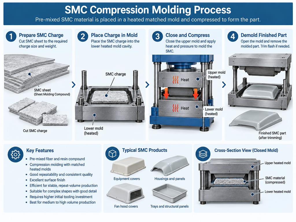
SMC is not simply a fiberglass sheet that is bent into shape. The charge, material flow, tool temperature, press conditions, venting, geometry, and cure behavior work together as a molding system. Rib features, bosses, wall transitions, inserts, and cosmetic surfaces require process-aware design.
Compared with manual open molding, SMC normally requires a larger tooling and equipment commitment. Its advantage is strongest when the product design is stable and repeated molding can use that investment effectively. A well-developed SMC process can support consistent geometry and efficient repeat production, but it is not automatically economical for an early prototype or a frequently changing part.
When SMC Makes Sense
SMC may suit repeat-volume programs for industrial covers, housings, panels, and structural or non-structural molded components when the geometry is compatible with material flow and compression tooling. Buyers should evaluate press and tool constraints, surface requirements, part handling, trimming, inserts, and the stability of future demand.
An SMC fan hood cover application illustrates a repeat molded housing whose geometry and production approach are tied to compression-molding requirements.
Key Differences OEM Buyers Should Consider
1. Tooling Investment
Hand lay-up normally starts with a less complex tool because only one principal molded face is required. RTM needs a sealed closed cavity and resin-transfer provisions. SMC needs durable matched tooling compatible with the press and molding conditions. Tooling cost should be evaluated against design maturity and expected program demand.
2. Production Quantity
Quantity changes how tooling is amortized and how much manual labor matters in each part. Lower or uncertain demand may favor process flexibility. Stable recurring demand can justify greater tooling and process-development effort. There is no universal volume breakpoint because part size, complexity, labor, finish, and tool life all affect the calculation.
3. Part Size and Geometry
Large open shells may be accessible for hand lay-up but difficult to enclose in a matched tool. RTM geometry must support preform loading, filling, venting, and demolding. SMC geometry must permit suitable charge placement and material flow under compression. Equipment and handling limits also matter.
4. Surface Finish
Hand lay-up typically provides one controlled mold-side surface; the open side has a different finish condition. RTM provides two mold faces and can improve control on both sides. SMC can provide repeatable molded surfaces when the compound, tooling, and process are developed for the required appearance. Paint preparation or secondary finishing may still be necessary.
5. Dimensional Repeatability
Manual laminate placement and resin application make hand lay-up more operator dependent. A stable RTM process can offer better control through a closed cavity. SMC matched tooling can support strong repeatability for a stable product. Actual capability must still be confirmed for the specific geometry, material, tool, and inspection plan.
6. Structural Requirements
The molding method alone does not define strength. Reinforcement type and orientation, resin selection, laminate thickness, local load paths, inserts, joints, cure, and defects all influence structural performance. The process must be able to produce the intended laminate consistently in the relevant areas. Resin selection also affects processing and finished-part requirements; see our guide to polyester, vinyl ester and epoxy resins.
7. Design Changes
Changes are generally easier to consider before complex matched tooling is committed. RTM and SMC tool revisions can affect both sides of the cavity and the established molding process. Buyers should freeze critical interfaces, draft, wall transitions, holes, inserts, and cosmetic requirements at the appropriate project stage.
8. Production Economics
Piece price alone is not enough. Review tooling, material utilization, labor, cycle workflow, secondary trimming, finishing, inspection, expected scrap risk, maintenance, forecast stability, and program life. The most economical route is the one that fits the complete production case, not necessarily the process with the lowest tooling or the fastest molding step.
Can the Same Fiberglass Part Be Made by Different Processes?
Sometimes, yes. A housing or cover may be technically feasible by more than one process. However, changing the process often changes the part definition and the surrounding manufacturing plan.
A hand lay-up version may use a one-sided mold and allow manual placement around local features. An RTM version needs a closed cavity, a reinforcement preform, resin-flow paths, vents, seals, and suitable draft. An SMC version needs charge-flow-compatible geometry, matched heated tooling, and features that can be filled and released reliably under compression.
As a result, the process decision may change:
- tooling construction and mold separation;
- laminate design and reinforcement form;
- nominal wall geometry and transitions;
- draft, radii, flanges, and edge details;
- insert type and insertion method;
- cosmetic surface definition;
- trim lines, holes, and secondary machining;
- inspection methods and production cost structure.
How DISLAB Reviews a Fiberglass Project
DISLAB’s project review may consider the drawing or CAD model, overall dimensions, geometry, expected quantity, application, service environment, required surfaces, structural expectations, mounting features, and the expected production program. The objective is to identify a practical material, tooling, and manufacturing direction for the specific inquiry.
Not every project or geometry is suitable for every process. A recommendation should follow feasibility review rather than a generic preference for hand lay-up, RTM, or SMC.
Information to Prepare Before Process Selection
Providing the following information helps a manufacturer compare process options on the same project basis:
- 2D drawing or 3D model
- Order quantity and expected recurring demand
- Overall dimensions and target mass, if relevant
- Cosmetic surface requirements for each side
- Structural loads and stiffness expectations
- Mounting points, inserts, interfaces, and datums
- Operating environment and exposure conditions
- Resin or reinforcement preference, if already defined
- Trim, drilling, painting, or assembly requirements
- Project stage and expected schedule
Forecast uncertainty should be stated openly. A program with an unproven design and uncertain demand may need a different tooling path from a mature product with stable repeat orders.
FAQ
Is RTM always better than hand lay-up?
No. RTM can provide a more controlled closed-mold process, but it also requires more tooling and resin-flow planning. Hand lay-up may be more practical for a prototype, a large custom shell, lower quantities, or a design that is still changing.
Is SMC suitable for low-volume production?
It can be technically possible, but the tooling and press commitment may be difficult to justify for limited demand. The decision depends on part complexity, surface and repeatability requirements, available tooling, program life, and the economics of alternative processes.
Can large fiberglass parts be made by hand lay-up?
Yes, many large shells and covers can be made by hand lay-up when the mold, laminate access, handling, cure, trimming, and inspection plan are appropriate. Size is only one selection factor; structural and production requirements still need review.
Does RTM provide a better finish on both sides?
RTM provides two mold faces and therefore a better opportunity to control both surfaces than a typical open-mold lay-up. The actual finish still depends on tool quality, surface system, reinforcement print-through, resin, filling, cure, and post-processing.
Can the same mold be used for hand lay-up and RTM?
Usually not without specific planning and modification. RTM needs a closed, sealed cavity with controlled spacing, injection, and venting provisions. A tool designed only as an open hand lay-up mold may serve as a design reference, but it should not be assumed to function as a complete RTM tool.
Which process is cheapest?
There is no universal answer. Hand lay-up may reduce initial tooling commitment but uses more manual labor. RTM and SMC can shift cost toward tooling and process development while improving repeat-production control. Compare total program economics rather than one cost element.
Which process provides the best dimensional consistency?
Closed matched-tool processes generally offer more opportunity for dimensional control than manual open molding. SMC and a stable RTM process can both provide strong repeatability, but actual capability depends on part geometry, material, tool construction, process control, cure, and the measurement plan.
How should an OEM choose between the three processes?
Start with the drawing, demand forecast, surface expectations, critical dimensions, structural requirements, design maturity, and target program economics. Then review the feasible tooling and laminate routes with the manufacturer before committing to a production process.
Need Help Evaluating a Custom FRP Part?
Share the drawing, quantity, application, environment, surface requirements, and project stage so the manufacturing route can be reviewed against the actual part.
Review DISLAB’s custom FRP fabrication capabilitiesThis article provides general process-selection guidance. Final material, tooling, laminate, and manufacturing decisions should be confirmed for the specific geometry, production program, and operating conditions.